The realization of a current loop in an electrical or automation cabinet is essential to acquire signals from sensors, measuring instruments and actuators. This activity involves a careful circuit and dimensional analysis. On the one hand it is necessary to allow the transmission of signals to I/O modules or PLCs, on the other hand it is necessary to connect power supplies and sensors with the right technique, i.e. avoiding overvoltages, overcurrents, impossibility to control the load or to have a sufficient number of wires for wiring. Below we illustrate the main connection techniques offered by the range of SENECA signal conditioners.
Current loops 0…20 / 4…20 mA
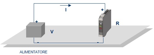
In order to circulate current I it will be necessary to have a power supply in the circuit with a voltage at least equal to or higher than V.
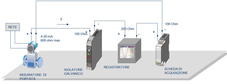
Current loops 0…20 / 4…20 mA with series equipment
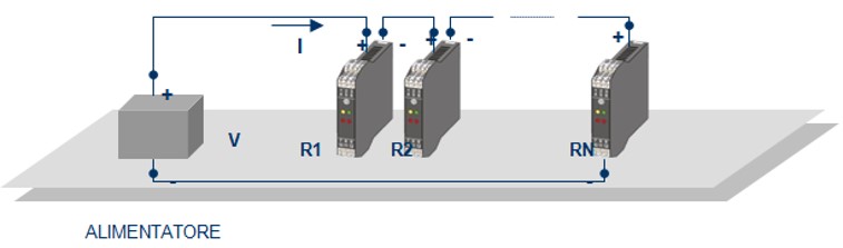
The total impedance of the circuit will be the sum of the input impedance of the single instruments, so a power supply with a voltage equal to or higher than V must be available.
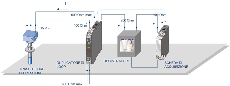
Current loop 0…20 / 4…20 mA with series equipment and transducer
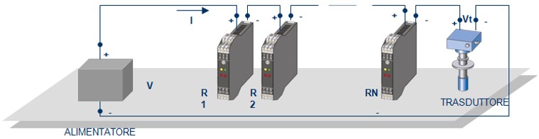
The total impedance of the circuit will be the sum of the input impedance of the single instruments, so a power supply with a voltage equal to or higher than V must be available.
Signal from active transducer
The transducer is “active” i.e. capable of generating current in the loop. As a rule, these transducers have power supply terminals separated from the current output terminals. The fundamental parameter to be known in this case is the maximum impedance (expressed in ohms) that the current output of the transducer can drive
Signal coming from transducer in 2-wire technique
In this case the transducer that is powered directly by the current circulating in the loop