 https://blog.seneca.it/wp-content/uploads/2022/03/00-TA.jpg
Current transducers are essential components for low and medium voltage energy monitoring. These devices, strengthened by their accuracy and ease of installation, allow the signal from the primary source to be converted and made available to other energy monitoring instruments, such as energy meters, network analyzers, power quality meters and other transducers. Applications range from current and absorption measurements for electric motors and control devices, to the detection of energy consumption, to the normalization of electrical signals into standard signals usable by data acquisition systems.
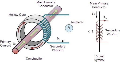
Not to be confused with current transducers, current transformers (CTs) reduce high voltage currents to much lower values, safely monitoring the actual electric current flowing in a transmission line using a standard ammeter.
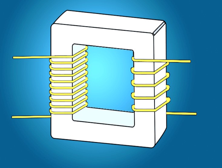
Generally speaking, current transformers are inductive sensors consisting of a primary winding, a magnetic core and a secondary winding.
Essentially, they allow a high current to be transformed into a lower one using a magnetic vector. In most CTs, the primary winding has far fewer turns than the secondary winding. The ratio of turns between the primary and secondary windings determines the current load reduction ratio.
Current transformers can reduce current levels from thousands of amps down to a standard output of a known ratio, typically to 1 or 5 amps for normal operation.
According to the primary winding we distinguish:
- Toroidal CTs (do NOT contain a primary winding. The line carrying the current flowing in the network is threaded through a window or a hole in the toroidal transformer)
- Wire-wound CTs (The primary winding of the transformer is physically connected in series with the conductor carrying the measured current flowing in the circuit).
- Bar-type CT (This type of transformer uses the actual cable or bus bar of the main circuit as the primary winding)
The main variables that must be considered when selecting an amperometric transformer are: - Cross section of the through-hole.
- Transformation ratio.
- Accuracy class in relation to the power required by the instrument connected to the transformer secondary.
SENECA solutions
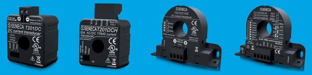
SENECA AC/DC Current Transducers T201 Series are devices able to convert the measured current value (up to 600 A) into an industrial standardized 4..20 mA or 0..10 V signal. Most models of the T201 Series are UL certified and feature low power consumption, convenient measurement scales settable via DIP-switch or software, and high accuracy. 16 models are available with different measuring principles: rectified average, magnetic balance (with patented technology), Hall Effect or TRMS with bipolar input range. Some models are equipped with RS485 ModBUS RTU interface and Micro USB port. The T201 range is appreciated for the versatility of power supply (even on measuring loops) and the low power consumption, which together with the negligible thermal drift, makes it extremely reliable. based on the principle of measurement SENECA offers:
Magnetic induction transducers
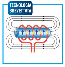
Transducers using magnetic induction measurement technology (SENECA international patent N° PD2009A000005) are long-life devices thanks to the measurement principle that avoids thermal drifts and exploits the generation of an induced current at the transducer output, through the variation of a magnetic field. They can be used directly without external shunts, even for pulsed currents.
Hall effect transducers
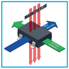
In Hall Effect measuring transducers, when a magnetic field is applied perpendicular to a conductor a voltage is generated transverse to the direction of current flow. Hall effect transducers are used as an alternative to shunts when high voltages and high galvanic isolations are involved.
SENECA range at a glance
| Model | Power Supply | Power Consumption | Through Hole Diameter | Accuracy Class | Measurement | Input Range | Ouput Range | Communication Interface | |
| 1 | T201 | Loop powered (5..28 Vdc) | < 21 mA | 12,3 mm | AC: 0,2% f.s. | Rectified average | 0..40 Aac | 4..20 mA | – |
| 2 | T201DC | Loop powered (6..100 V) | < 21 mA | 12,3 mm | DC: 0,2% f.s | Magnetic balancing (patented technology) | 0..40 Adc | 4..20 mA | – |
| 3 | T201DC100 | Loop powered (6..100 V) | < 21 mA | 20,8 mm | DC: 0,2% f.s | Magnetic balancing (patented technology) | 0..100 Adc | 4..20 mA | – |
| 4 | T201DCH | 10..28 Vdc | < 25 mA | 12,3 mm | 0,5% f.s. (DC bipolar, AC/DC TRMS) | Hall Effect | ± 50 Aac/dc | 0..10 V | – |
| 5 | T201DCH100 | 12..28 Vdc | < 25 mA | 20,8 mm | 0,5% f.s. (DC bipolar, AC/DC TRMS) | Hall Effect | ± 100 Aac/dc | 0..10 V | – |
| 6 | T201DCH300 | 12..28 Vdc | < 25 mA | 20,8 mm | 0,5% f.s. (DC bipolar, AC/DC TRMS) | Hall Effect | ± 300 Aac/dc | 0..10 V | – |
| 7 | T201DCH50-LP | Loop powered (9..28 Vdc) | < 22 mA | 12,3 mm | AC: 0,5% f.s. DC: 1% f.s. | Hall Effect | ± 50 Aac/dc | 4..20 mA loop powered | – |
| 8 | T201DCH100-LP | Loop powered (9..28 Vdc) | < 22 mA | 20,8 mm | AC: 0,5% f.s. DC: 1% f.s. | Hall Effect | ± 100 Aac/dc | 4..20 mA loop powered | – |
| 9 | T201DCH300-LP | Loop powered (9..28 Vdc) | < 22 mA | 20,8 mm | AC: 0,5% f.s. DC: 1% f.s. | Hall Effect | ± 300 Aac/dc | 4..20 mA loop powered | – |
| 10 | T201DCH50-M | 12..28 Vdc | < 25 mA | 20,8 mm | 0,5% f.s. (DC bipolar, AC/DC TRMS) | Hall Effect | ± 50 Aac/dc | 0..10 V | RS485 ModBUS |
| 11 | T201DCH100-M | 12..28 Vdc | < 25 mA | 20,8 mm | 0,5% f.s. (DC bipolar, AC /DCTRMS) | Hall Effect | ± 100 Aac/dc | 0..10 V | RS485 ModBUS |
| 12 | T201DCH300-M | 12..28 Vdc | < 25 mA | 20,8 mm | 0,5% f.s. (DC bipolar, AC TRMS) | Hall Effect | ± 300 Aac/dc | 0..10 V | RS485 ModBUS |
| 13 | T201DCH50-MU | 11,5..28 Vdc | 21 mA excluding load | 20,8 mm | 0,5% f.s. (DC bipolar, AC/DC TRMS) | Hall Effect | ± 50 Aac/dc | 0..10 V | RS485 ModBUS / Micro USB |
| 14 | T201DCH100-MU | 11,5..28 Vdc | 21 mA excluding load | 20,8 mm | 0,5% f.s. (DC bipolar, AC/DC TRMS) | Hall Effect | ± 100 Aac/dc | 0..10 V | RS485 ModBUS / Micro USB |
| 15 | T201DCH300-MU | 11,5..28 Vdc | 21 mA excluding load | 20,8 mm | 0,5% f.s. (DC bipolar, AC/DC TRMS) | Hall Effect | ± 300 Aac/dc | 0..10 V | RS485 ModBUS / Micro USB |
| 16 | T201DCH600-MU | 11,5..28 Vdc | 21 mA excluding load | 35 mm | 0,5% f.s. (DC bipolar, AC/DC TRMS) | Hall Effect | ± 600 Aac/dc | 0..10 V | RS485 ModBUS / Micro USB |