 https://blog.seneca.it/wp-content/uploads/2020/07/signal4.jpg
In many factory and process automation applications the problem is to implement the conversion of one signal at the input to another standardized signal at the output of a device. In addition, it is essential to have excellent conditioning electronics for isolation, amplification, linearization and conversion of signals from low-level sensors, so that data-loss-free transmission can be achieved even over long distances, in noisy environments and with many different loads.
| Sensor / Signal Type | Application |
| Thermocouple B, C, E, J, K, N, R, S, T | Temperature measurement |
| Thermoreistance Pt100, Pt500, Pt1000, Ni100 | Temperature measurement |
| DC Current 4-20mA, 1-5A, 0-100µA, 0-1mA, 1-5mA | Management of standard control signals or sensor output |
| DC Voltage 1-5V, 0-10V, +/-5V, +/-10V, 0-100V, 0-500V | Management of standard control signals or sensor output |
| Strain gauge bridge 0-10mV, 0-20mV, 0-30mV, ±10mV, ±50mV | Weighing, pressure, torsion, compression management |
| Potentiometer 0-100 Ohm, 0-500 Ohm, 0-1000 Ohm, 0-10 KOhm | Setpoint adjustment, position control, tank level |
| Frequency/ Pulse Sine wave, square wave, triangular wave or pulse peaks | Proximity sensor management for speed, flow and counting |
| Digital Contact, Reed, NPN, PNP, Namur, Photoelectric, Hall, Var. Reluctance, 24 V pulse, TTL, Volumetric Counter | Alarm thresholds, status switches |
| AC Current 0-100mA, 0-1A, 0-5A | Electrical power management or load measurement |
| AC Voltage 0-500mV, 0-24V, 0-120 V AC | Electrical power management or load measurement |
Conversion to current, voltage and resistance
In relation to the levels of electrical signal transmission quantities, there are standardizations for the industrial environment that allow the connection of heterogeneous devices by type and manufacturer. For example, analog signals over long distances are normally transmitted with the so-called current loop in the 4-20 mA range.
Other standard signal levels, normally used when transmission distances are short (e.g. from the edge of the machine to the control panel), are in the range ±10 V or in measuring ranges up to 1,000 Ohm, in the case of converters that accept input signals for resistance measurement with connection to rheostats or potentiometers.
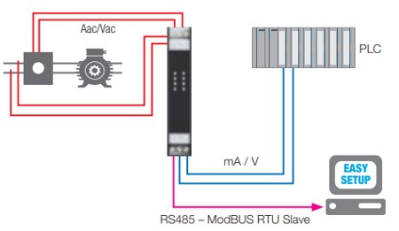
Electrical measurement converters
An important category of signal conditioners is represented by electrical measurement converters that measure voltage and current (alternating and/or continuous) values by converting them into a normalized current or voltage signal at the output terminals, proportional to the input value. The scaling parameters of the inputs and outputs are selectable via software or DIP switch.
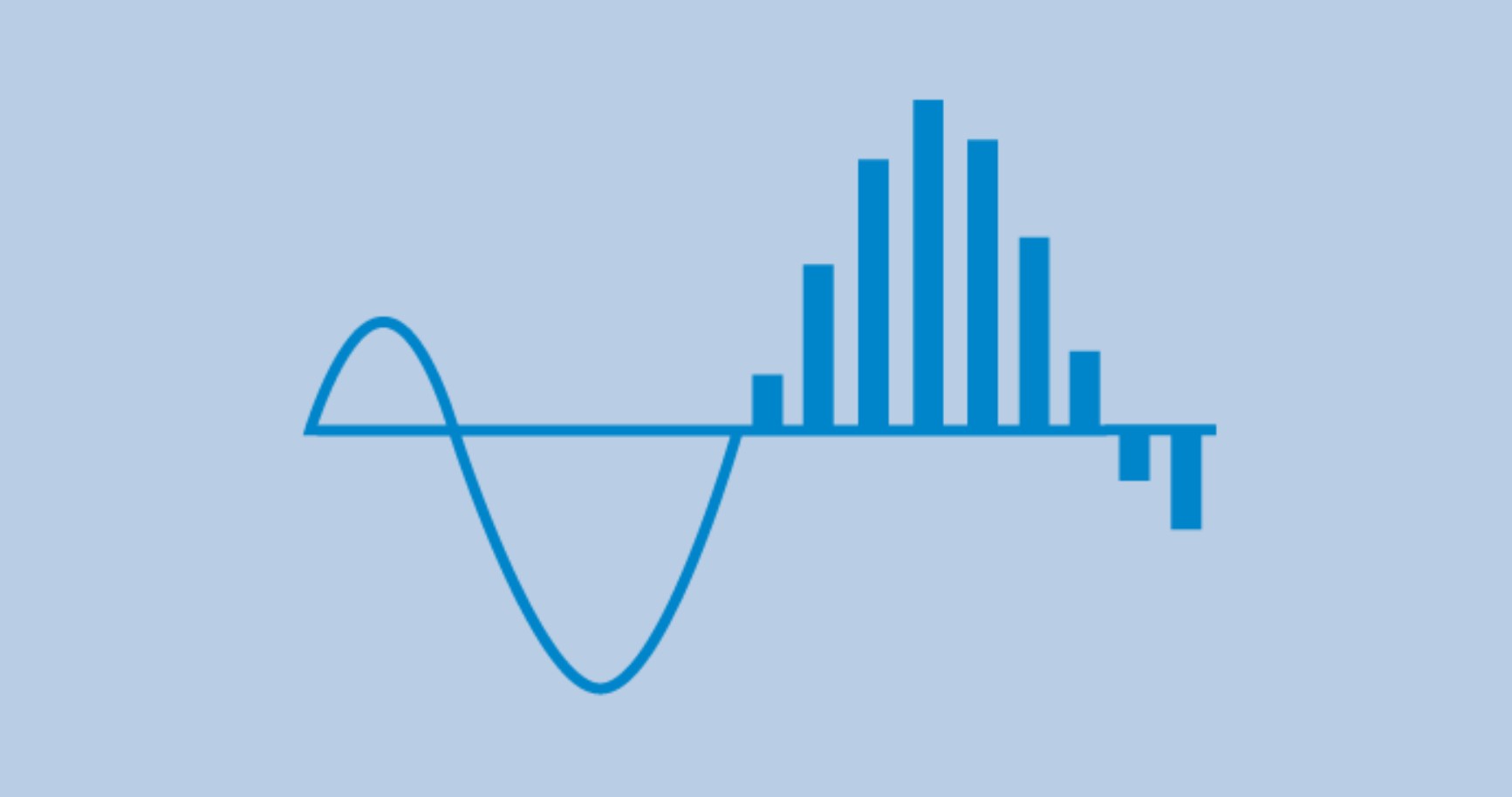
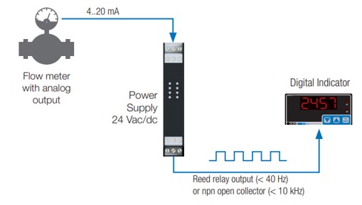
Frequency conversion
The conversion of signals to frequency, on the other hand, involves devices that involve measuring frequency, reading pulses in a constant time interval), counting the number of revolutions, speed, production batches or waste. Acquisition and transmission are carried out by measuring the period or frequency of impulsive signals coming from industrial sensors such as: photocells, proximity switches, one-way incremental encoders, reed contacts, etc. Another typical use is the conversion of the speed of a gear wheel through magnetic pick-up, photoelectric sensors, Namur to send data to the analog inputs of PLC and/or DCS. Most voltage/current-frequency converters accept an impulsive signal at their input and produce a voltage output whose amplitude is directly proportional to the frequency of the input signal.
Conversion with relay outputs
The applications of converters with relay outputs concern the activation of thresholds, implementation and switching of digital outputs (alarms, transistors, relays). Typical applications involve the control of impulsive or analog inputs, acoustic/visual alarm management, remote controls, management of setpoints, thresholds, timings and status switching.
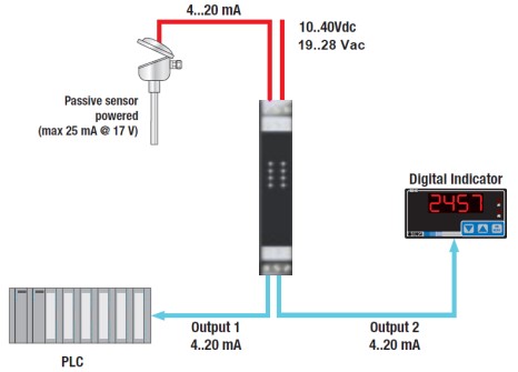
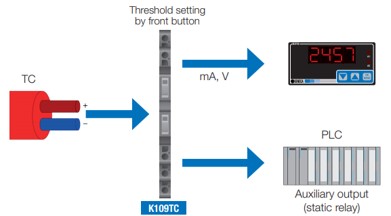
Temperature conversion
In measurements with temperature-dependent resistors, a current of a few milliAmperes is passed through a constant current source in the signal converter. The voltage drop in the resistor (two-conductor circuit) is measured via an amplifier. In order to take the voltage drop on the conductors into account, the voltage drop of the return cable is measured and calculated by doubling the value (three-conductor circuit). This simulates the resistance of the supply and return cable.
In the case of thermocouples, on the other hand, cold junction compensation is the most popular technique to obtain accurate measurements. When a thermocouple is connected to a data acquisition system, it is necessary to know the temperature at the connection point to calculate the actual temperature that the thermocouple is measuring. In temperature sensing with thermocouples, the problem of thermovoltage formation at the clamping points of the signal converter arises due to the diversity of materials between cable and conductor rod. This voltage neutralizes the thermocouple voltage. To compensate for the resulting change in the measured value, the temperature is measured at the clamping point. The signal converter then reads the measured value at that point and calculates it from the measured value. This technique is known as the cold junction compensation method.
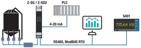
Converters for measuring bridges
Another widely used conditioning technique is that of measurements based on strain-gauge bridges such as weight, torsion, stress, etc. Typically the weight and load of an external measuring bridge are read by the signal conditioner and converted into a normalized analog signal. The bridge measurement converters process input signals in the milliVolt range.
In industrial weighing applications, load cells under a “measuring bridge” generate a voltage signal which is amplified, isolated and converted into a linear voltage or direct current output for further processing by the weighing system.
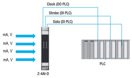
A/D / Multiplexing conversions
Through the A/D (analog/digital) conversion we obtain, starting from an input voltage that can assume a certain value within a certain dynamic, a bit string that, according to a certain encoding, is linked to the input voltage itself. The encodings used in converters are many, but simplifying it we can assume that the number obtained from the conversion is proportional to the input voltage. A/D conversion is fundamental in almost all signal acquisition and processing systems. In fact, most modern industrial instrumentation works with numerical signals. In particular through multiplexing, a measurement system is able to sequentially route multiple signals in a single digitizer, thus offering a low-cost method to increase the number of channels in the system. A multiplexer consists of a set of diverters or switches and offers an attractive cost reduction by using only one A/D converter per N input.